
Electrical
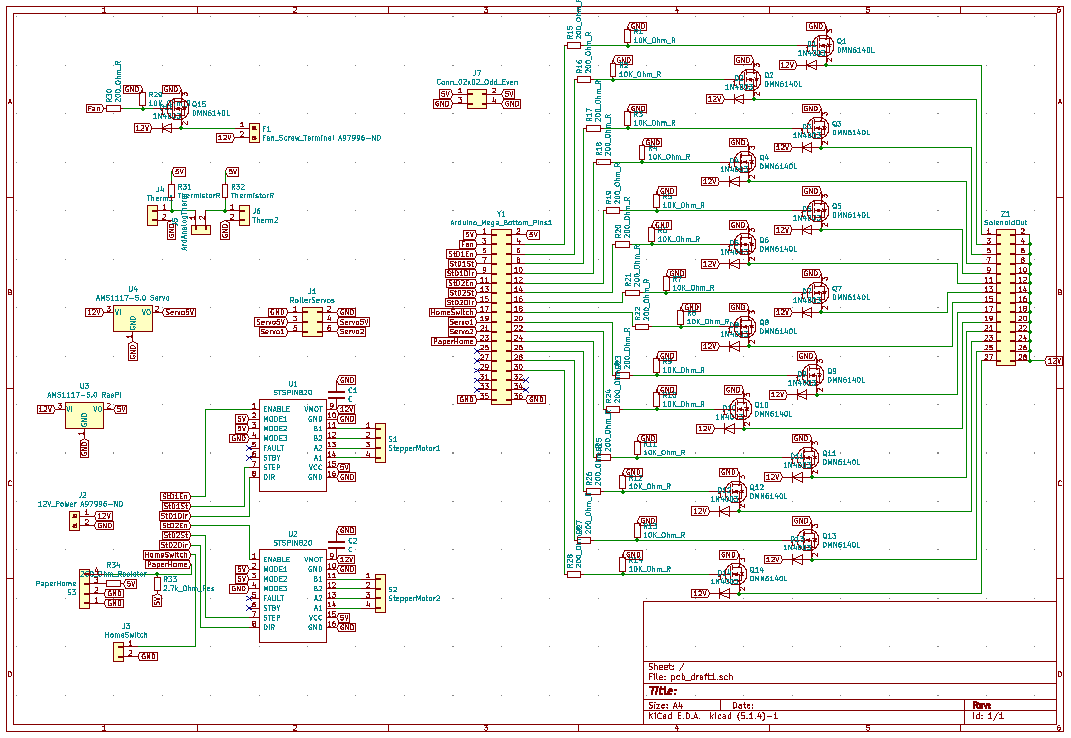
Our major current demand came from powering the 14(!) solenoids on the PortaBraille. Each solenoid draws 1 amp (A) of current each, so we needed to have a power supply capable of drawing that much current. We purchased a 12 volt (V), 30 A power supply to satisfy this requirement.
Pictured above is the final circuit diagram for the PCB.
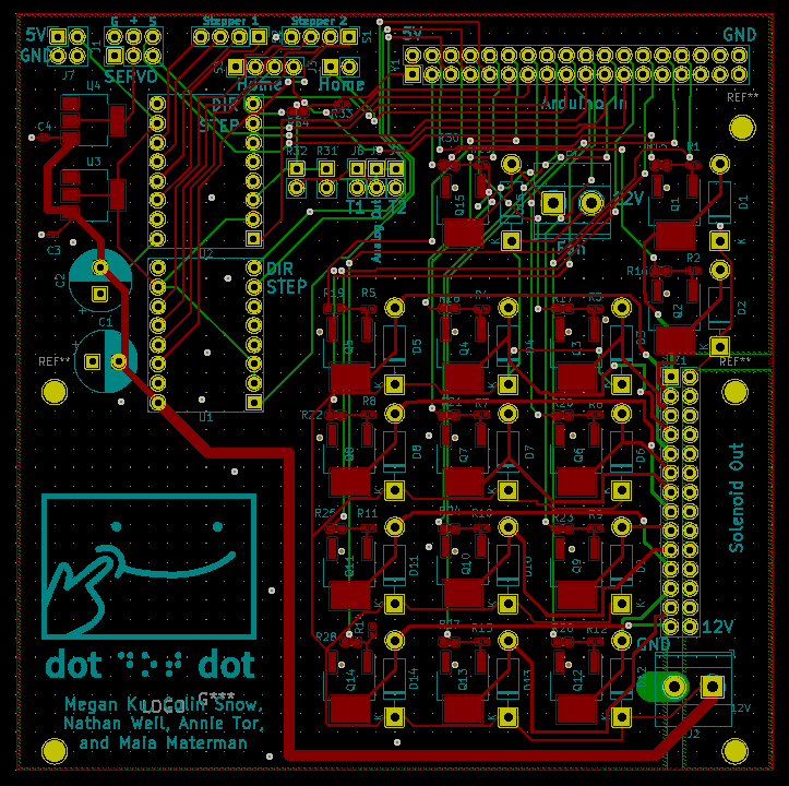
Pictured above is the final layout of the PCB. We adjusted trace widths to support the high current draw from the power supply.
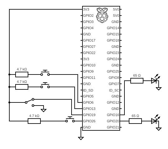
The circuitry for the interface was housed on a protoboard, allowing us to easily adjust our design to the physical shape of the interface quite easily. The Raspberry Pi collected data on the states of the buttons and sound switch and turned on and off the LEDs.
This is the circuit diagram for the interface.