Mechanical
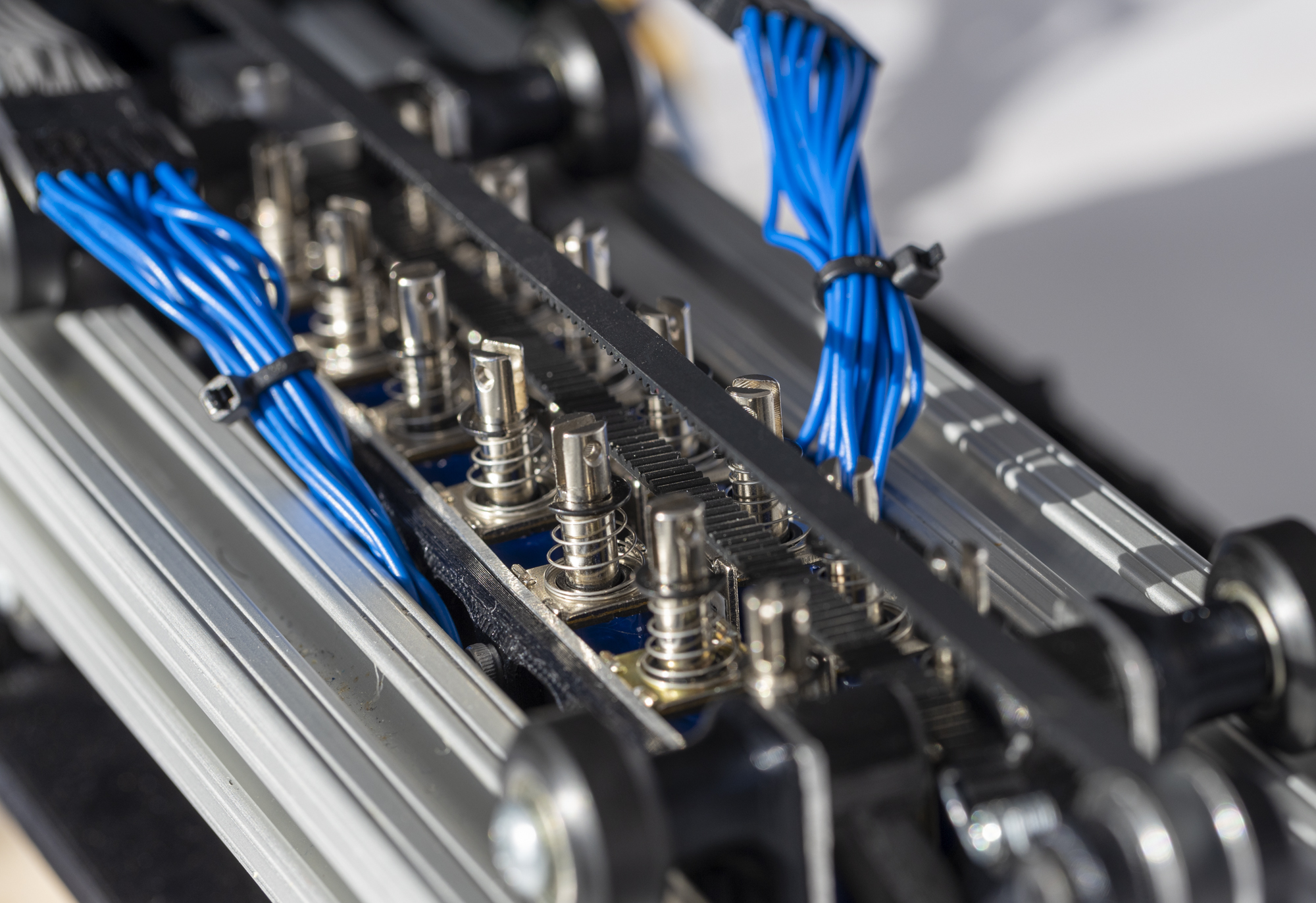
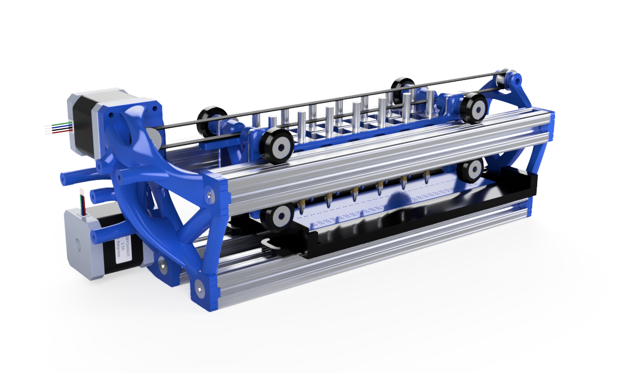
The printer’s core structure is made up of four 80/20 aluminum extrusions. They are bolted together with 3d printed side plates sculpted in Fusion 360. The side plates mount the two stepper motors that control paper roller movement and gantry movement. On the top two bars, a gantry is mounted on roller bearings to the 80/20 bars. The gantry is a rigid structure made from 3d printed PLA plastic and sheet aluminum, held together with 10-24 screws and threaded inserts. It is driven back and forth by a belt drive from a Nema 17 stepper motor. Mounted in the gantry are 14 solenoids. Each solenoid has a small standoff and pin attached to the bottom. When current is passed through the solenoid coil, the pin punches down onto a commercially available braille punch plate. This creates braille dimples in paper as it passes through.
To move the paper, a stepper motor drives a paper roller sourced from a broken inkjet printer via a flex coupling. As paper is fed in, rubber rollers move it to precise positions, allowing the accurate positioning of braille dots vertically on the page. The paper roller moves the paper across a paper tray which is mounted to the lower pair of 80/20 bars. The paper tray has an inset slot for the punch plate and an acrylic beam to help hold the paper down.
Two sensors are mounted to the robot, a limit switch acting as a home position for the gantry, and a photogate interrupt sensor that detects when the paper has been fully loaded. The limit switch is mounted to the motor mount side plate, and the photogate is inset into the paper tray.
The Arduino Mega, custom solenoid driver board, and Raspberry Pi 3 B+ are all bolted to the motor mount side plate in order to ensure durability in transport. A 5v 2A power supply and a speaker are attached under the motor mount side plate in order to keep packaging small.
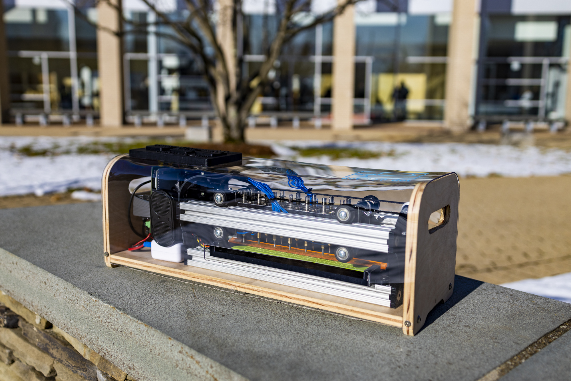
To contain the printer and make it portable, we fabricated a plywood and polycarbonate enclosure. The wood base plate and side panels were fabricated using traditional shop tools, and are attached to with threaded inserts and 80/20 hardware into the core frame of the printer. The polycarbonate shell was heat bent by clamping it to the plywood and slowly applying hot air from a heat gun. The female USB port for text file input, the braille friendly user interface, and a cooling fan are all attached to the polycarbonate shell.